Two Bad Sensors and a Kalman Filter
On the OSU DAM Robotics rover team, one of the things I worked on was an extended Kalman filter that fused a stereo depth camera with an IMU, so the rover could keep track of where it was while it drove itself.
Most explanations of Kalman filters I’ve seen start with a lot of matrices. I think it’s easier to understand if you first watch each sensor fail on its own, so that’s how this post goes.
I can’t post the team’s code, so I rebuilt the core of it as a small simulation where I know exactly where the rover really is, which means I can measure exactly how wrong each method gets. All the numbers in this post come from that sim, and the code is on GitHub as rover-ekf-sim.
The setup 
The simulated rover drives about 2.4 laps of a wobbly loop with a 12 m radius, 181 m total over 180 seconds. It has two sensors and neither of them is very good.
The IMU runs at 100 Hz. The gyro measures how fast you’re turning and the accelerometer measures how fast you’re speeding up. Both are noisy and both have a bias. The gyro reads 0.02 rad/s too high (about 1.1 degrees per second), which is a realistic offset for a cheap uncalibrated MEMS gyro.
The stereo camera runs at 10 Hz. It recognizes eight markers at known spots around the loop (think ArUco tags) and gives you the range and bearing to each one it can see. It only sees markers within 15 m and within 55 degrees of straight ahead, and its range measurement gets bad quickly. Stereo depth comes from the disparity between the two images, and the disparity gets smaller the farther away something is, so the error grows with the square of the distance. At 10 m the range is off by about a meter.
With eight markers around the loop, the camera only sees two or more of them in about half of its frames. In one run, 208 of the 1,800 frames had no markers in view and 700 had just one.
Getting the sim right took me longer than the filter did. My first track drove the rover straight out of the marker field, so the camera saw nothing for basically the whole run, which isn’t a very useful test of a camera. Now the track loops around inside the markers.
Just trust the IMU? 
The simplest thing you can do with an IMU is dead reckoning. You start at a known spot, add up the gyro readings to get your heading, add up the accelerometer readings to get your speed, and add up speed in the direction you’re heading to get your position.
x += v * np.cos(theta) * dt
y += v * np.sin(theta) * dt
theta += gyro * dt
v += accel * dt
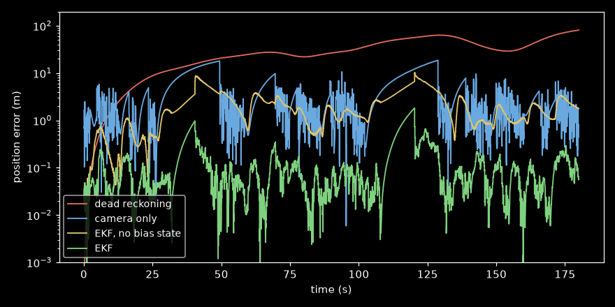
Over 20 runs the median error was 27.7 m, and at the end the rover was 81 m from where it actually was, which is pretty bad for a loop with a 12 m radius.
Most of that comes from the heading. By the end it was off by 206.6 degrees, which is almost exactly 0.02 rad/s times 180 seconds. A small constant bias added up 18,000 times gives you a heading that’s wrong by more than half a turn. Position is built from the heading, so the heading error keeps sending you off in the wrong direction, and that error gets added up too.
So the IMU is nice and smooth, but after a few minutes it’s way off.
Just trust the camera? 
The camera can’t drift, since every frame is measured against markers that don’t move. So for each frame that saw at least two markers, I solved for the position and heading that best matched what the camera saw, and between those frames I held onto the last answer. The first version of that solver sometimes blew up and put the rover something like
That gave a fix in 45% of frames, with a median error of 2.25 m and a worst case of 18.7 m. There’s no drift, but it’s noisy and has a lot of gaps. You can see the gaps in the error plot as a sawtooth pattern. Every time the camera loses the markers, the rover drives away from its last fix until it sees two markers again.
Combining them 
The IMU is great over a fraction of a second and bad over a minute. The camera doesn’t drift, but it’s noisy, slow and blind about half the time. What you want is the smoothness of the IMU with the camera correcting it.
To do that you keep track of how unsure you are about each estimate, not just the estimate itself. Say you have two guesses for the same thing,
The combined variance is smaller than either one, so two bad guesses give you a better one, which still feels a bit like cheating to me. You can also write the same thing as a correction.
That
A Kalman filter just does that over and over. When you predict with the IMU the uncertainty grows, and when you update with the camera it shrinks. Instead of a single variance it keeps a whole covariance matrix
The “extended” part 
A regular Kalman filter assumes everything is linear, and a rover isn’t. Driving forward changes
atan2.
The extended Kalman filter handles this by linearizing around wherever it currently thinks it is. At every step you take the Jacobian of the motion model (
x, y, th, v, bg = s
F = np.eye(5)
F[0, 2], F[0, 3] = -v * np.sin(th) * DT, np.cos(th) * DT
F[1, 2], F[1, 3] = v * np.cos(th) * DT, np.sin(th) * DT
F[2, 4] = -DT
s = np.array([x + v * np.cos(th) * DT, y + v * np.sin(th) * DT,
              th + (gyro[k] - bg) * DT, v + acc[k] * DT, bg])
P = F @ P @ F.T + Q
The update runs for every marker the camera sees.
dx, dy = LANDMARKS[j] - s[:2]
q = dx * dx + dy * dy
rh = np.sqrt(q)
h = np.array([rh, np.arctan2(dy, dx) - s[2]])      # what we expect to see
H = np.array([[-dx / rh, -dy / rh, 0, 0, 0],
              [dy / q, -dx / q, -1, 0, 0]])
R = np.diag([range_sigma(rh) ** 2, BEARING_SIGMA ** 2])
innov = np.array([r, b]) - h                         # what we actually saw, minus that
innov[1] = wrap(innov[1])
S = H @ P @ H.T + R
K = P @ H.T @ np.linalg.inv(S)
s = s + K @ innov
I_KH = np.eye(5) - K @ H
P = I_KH @ P @ I_KH.T + K @ R @ K.T
With just four numbers in the state (
Estimating something nothing measures 
So I added the gyro bias to the state as a fifth number. The heading update becomes
There’s no sensor that measures
This was the biggest improvement by far. The median error went down to 0.08 m and the RMS to 0.30 m, and the worst point over three minutes of driving was 1.92 m. At the end of one run the filter’s bias estimate was 0.0201 rad/s and the real value was 0.02, which was a lot closer than I expected.
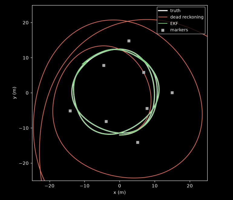
It’s also worth checking whether the filter is honest about how unsure it is. If its error estimates are right, the real error should be inside two standard deviations about 95% of the time. Here it’s 90%, which is pretty close, but it wasn’t at first. My first
The wrap line 
If you look at the update code again, there’s one line that doesn’t look very important.
innov[1] = wrap(innov[1])The innovation is the difference between the bearing the camera measured and the bearing the filter expected. Angles wrap around, so 179 degrees and -179 degrees are only 2 degrees apart, but if you just subtract them you get 358.
When I removed that line, the filter was happy for 23 seconds. Then at 23.5 s the camera saw a marker a little past due west of the rover, which is right where atan2 jumps from +180 to -180. The measured bearing was 57.3 degrees and the filter’s prediction was -305.0 degrees, which point in basically the same direction, 2.3 degrees apart. The subtraction gave 362.3 degrees though.
The filter believed it and applied a correction for being off by a full turn, and it never recovered after that. The median error over 20 runs went from 0.08 m to over a kilometer.
Anyway 
The thing I keep thinking about is that a Kalman filter isn’t really averaging. It weighs the model against the measurement based on how much you trust each one, and most of the actual engineering is in deciding how much to trust each one. So
The bias part surprised me the most. I didn’t expect that adding a variable nothing measures would be the biggest improvement, but it makes sense since the filter can only correct an error if there’s somewhere in the state for it to go.
Oh yeah, and remember to wrap your angles.